APRS tracker interfacing
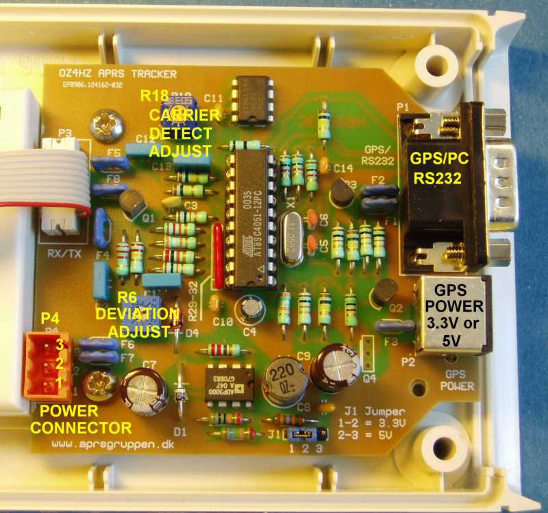
Connection at P4 (Power connector) you have 2 options :
1. Battery operation (4x 1.5V AA cells):
Jumper (J1) set to 5V use pin 3 for positive (+) and pin2 for negative (-)
and remark !!!! Battery negative is NOT GND
Jumper (J1) set to 3.3V use pin 3 for positive (+) and pin1 for negative (-)and now negative pin is GND
2. 12V operation i.e car battery
For both 3.3V or 5V use pin 3 for positive (+) and pin1 for negative (-)
and now negative pin is GND
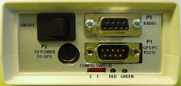
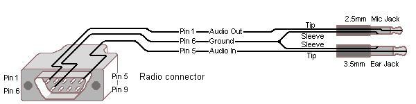
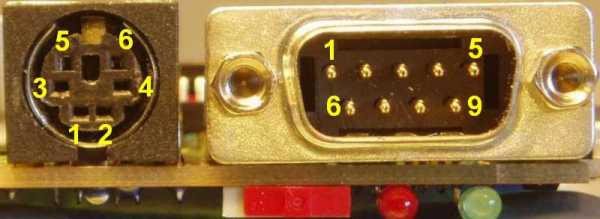
Connector P5 (9 pole female DSUB) is used to connect the tracker to the radio transceiver.
Connect TX MOD (TX Audio) (P5 pin1) to the radio's mic input.
If the transmitter is activated when the microphone input is grounded ( most handheld radios) leave R7 in place and
PTT (P5 pin3) is not needed.
For other transmitters PTT (P5 pin3) is needed and connected to the transmitters PTT in.
Connect TX MOD (P5 pin1) to the transmitters mic input and remove resistor R7 (2.2K)
and connect GND (P5 pin6) to the radio's GROUND.
The variable resistor R6 is used to adjust the frequency deviation.
Connect RX AF (P5 pin5) to the receivers AF output
The variable resistor R18 is used to adjust carrier detect sensitivity
An example of the connection to a handheld radio (ICOM ,YAESU) is shown below
Connector P1 is used for connection to a PC or a GPS unit and fits directly to a BR304 GPS unit Get BR304 Datasheet here
The GPS unit BR304 has been replaced by BR355 BR355 Datasheet but this unit has an 6 pole mini DIN connector
for both power and data connections.
A conversion cable is available to split power and RS232 connections.(see below)
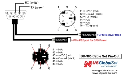
If you want to connect the BR355 GPS to the tracker without the conversion cable a small modification of the pcb is needed.
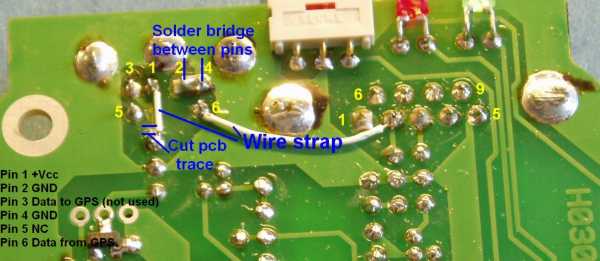
REMARK !!!! Pin numbers on P2 (Power to GPS) on the schematic has been changed to the pin-out
in the drawing of the BR355 GPS unit !!! No change has been made to the pcb
and after this connected to a GPS unit with serial interface (RS232).
All setup parameters are stored in an EEPROM so it is only nesesary to run the setup program once.
If the GPS can be connected directly to the PC's serial port - it can also be connected directly to the tracker.
Home